
Safety-by-Wire® — When the Safe State Means Continuing to Drive
The Dual-Channel Signal Path
Fully Fail-Operational by Design: The Architecture Behind Safety-by-Wire®
Part 1 of this series laid out the standards landscape; Part 2 presented the consolidated catalog of objectives—all the way up to ASIL D for steering, braking, and propulsion. Now we’re getting down to specifics: How do these objectives translate into technical structures? The answer begins with an assumption that must be abandoned. As long as a human is behind the wheel, a system is allowed to shut down in the event of a failure—the driver takes over. In highly automated and driverless operation, this fallback level no longer exists. The safe state is then no longer “off.” It means: maintaining control. Back in March, we argued why fail-safe is not enough. This article shows how Safety-by-Wire® implements this requirement architecturally—as a Fully Fail-Operational Design.
At a Glance
- Without a driver as a fallback, the most important parameter of the safety architecture changes: The safe state is no longer shutting down, but maintaining control of the vehicle.
- Two conceptual stages lead from the catalog of objectives to the structure: The functional safety concept distributes the objectives across functions, while the technical safety concept translates them into architecture.
- The architecture of NX NextMotion is based on end-to-end redundancy: two independent ASIL-D channels across the entire chain of action, redundant sensor systems with 2oo3 voting, and continuous diagnostics at all levels.
- Degradation instead of shutdown: Faults lead to defined, tested states of reduced functionality—within specified fault tolerance times and without loss of controllability.
- “Fail-operational” is only a robust concept when it is fully thought through. This is precisely what “Fully Fail-Operational” stands for: completeness across four axes—function, channel, control source, and power.
From Goal to Structure: Two Conceptual Levels, One Path
There are two translation steps between a safety goal and a printed circuit board. The functional safety concept assigns functions and mechanisms to each goal: What must the system do to achieve the goal—detect, control, degrade? The technical safety concept then translates these functions into architecture: channels, sensors, computation paths, diagnostics, and interfaces. Both steps sound like methodological theory. In fact, they are the point at which it is determined whether a system merely claims to be safe or is actually safe—because every architectural decision must be traceable back to an objective from the catalog. This traceability was the unspoken promise from Part 2. Here, it is fulfilled.
Fail-safe is a thing of the past: Why shutting down isn’t an option
The classic safety logic of mechanical and automotive engineering offers a tried-and-true response to errors: a safe stop. Valve closed, power off, system halted. This logic works as long as a standstill is safe—or a human can take over. A driverless vehicle in the center lane of a highway meets neither of these conditions. Neither does a mobile crane that suddenly comes to a stop while swinging.
Motion control for automated vehicles is therefore subject to a stricter requirement: The system must continue to function after a failure—at least long enough and well enough to bring the vehicle under control into a truly safe state, such as a low-risk maneuver leading to a safe stop at a suitable location. This is exactly what “fail-operational” means. It is not a comfort level above “fail-safe,” but rather a different architectural philosophy: safety through availability rather than safety through shutdown.
Systematic redundancy: two channels, three sensors, one principle
Availability in the event of a failure is not achieved through better components, but through structure. The architecture of NX NextMotion follows three principles to this end:
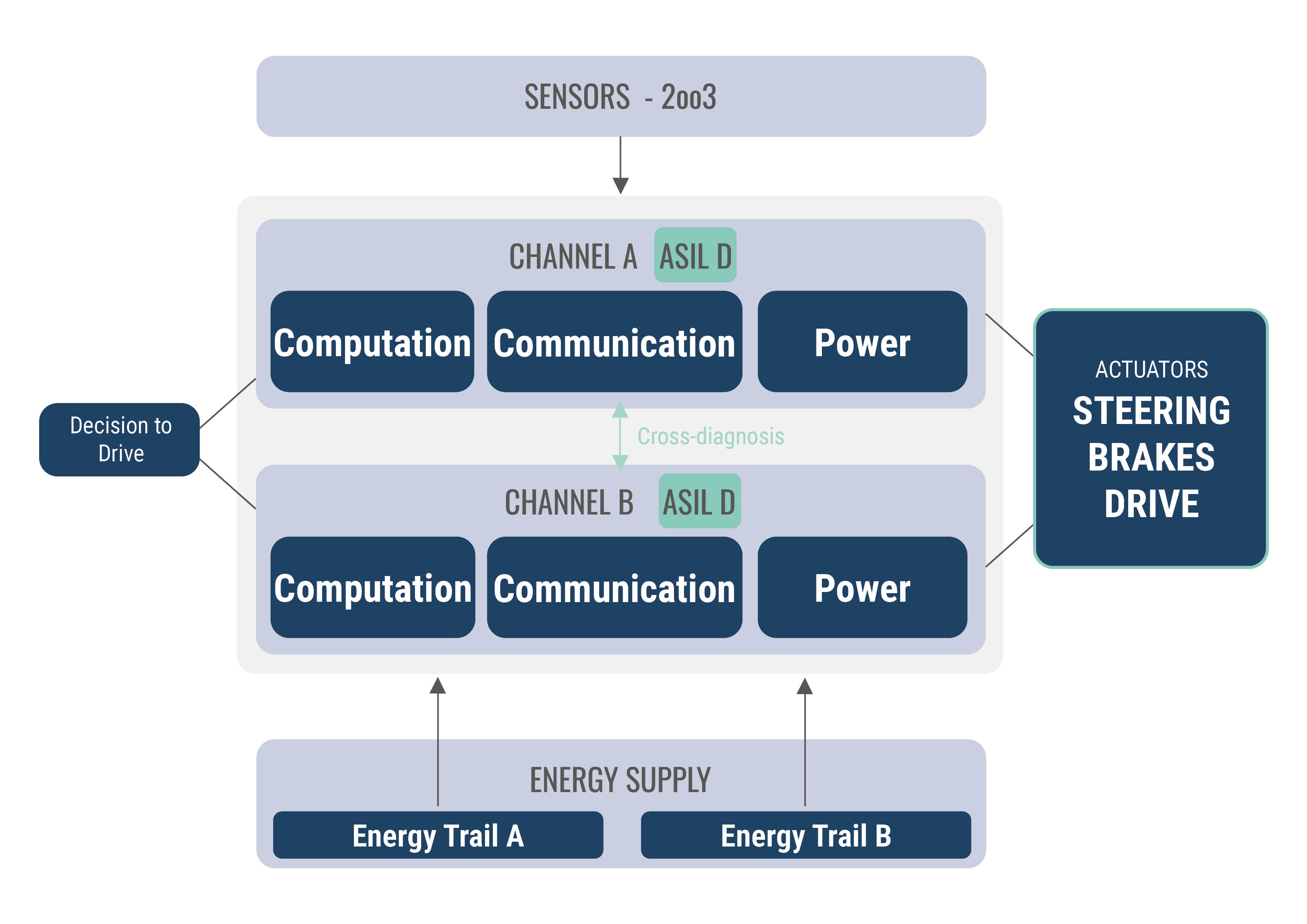
- Consistent dual-channel design. Two independent channels, each designed to ASIL D, run through the entire chain of operation—computing, communication, and control. The key word here is “end-to-end”: Two computers that share a connector, a bus system, or a power supply are not two channels, but a single shared fault with two enclosures. Therefore, it is not the control unit that is evaluated, but the chain: Sensors, computing, communication, power control, and actuators collectively meet the target rate for the highest safety level—less than 10 FIT—per channel.
- Redundant sensor systems with voting. Safety-critical parameters are measured multiple times and evaluated using the 2oo3 principle: If the signals diverge, the majority prevails—and the divergent path is flagged as suspicious without interrupting operation.
- Diagnostics at all levels—down to the individual processing unit. Monitoring does not stop at the channel boundary: Four microcontrollers, each with four lockstep cores—16 lockstep cores in total, eight on each side—monitor themselves and each other through plausibility checks, health monitoring, and comparison of the processing paths among themselves. A detected error is manageable. A latent error is the real danger—the architecture is therefore designed to uncover latent errors before a second one occurs. (Graph, see above)
Degradation: continues in a controlled manner, not abruptly
Redundancy answers the question of whether a system can continue to operate after a failure. The degradation concept answers how. Instead of a binary transition from “all” to “nothing,” the architecture defines graduated states of reduced functionality: full performance, limited operation, and risk-minimized maneuvers. Every transition is specified, every state is tested—and every change must be completed within defined fault tolerance times before a hazard can arise.
This sounds self-evident, but it isn’t. The difference between a specified and a mastered degradation path only becomes apparent under load: during a dual failure, during a “ ” transition while maneuvering, or when communication with the driving decision-making level is disrupted. It is precisely these cases that belong in the design—not in the excuses.
Fully Fail-Operational: The Four Axes of Completeness
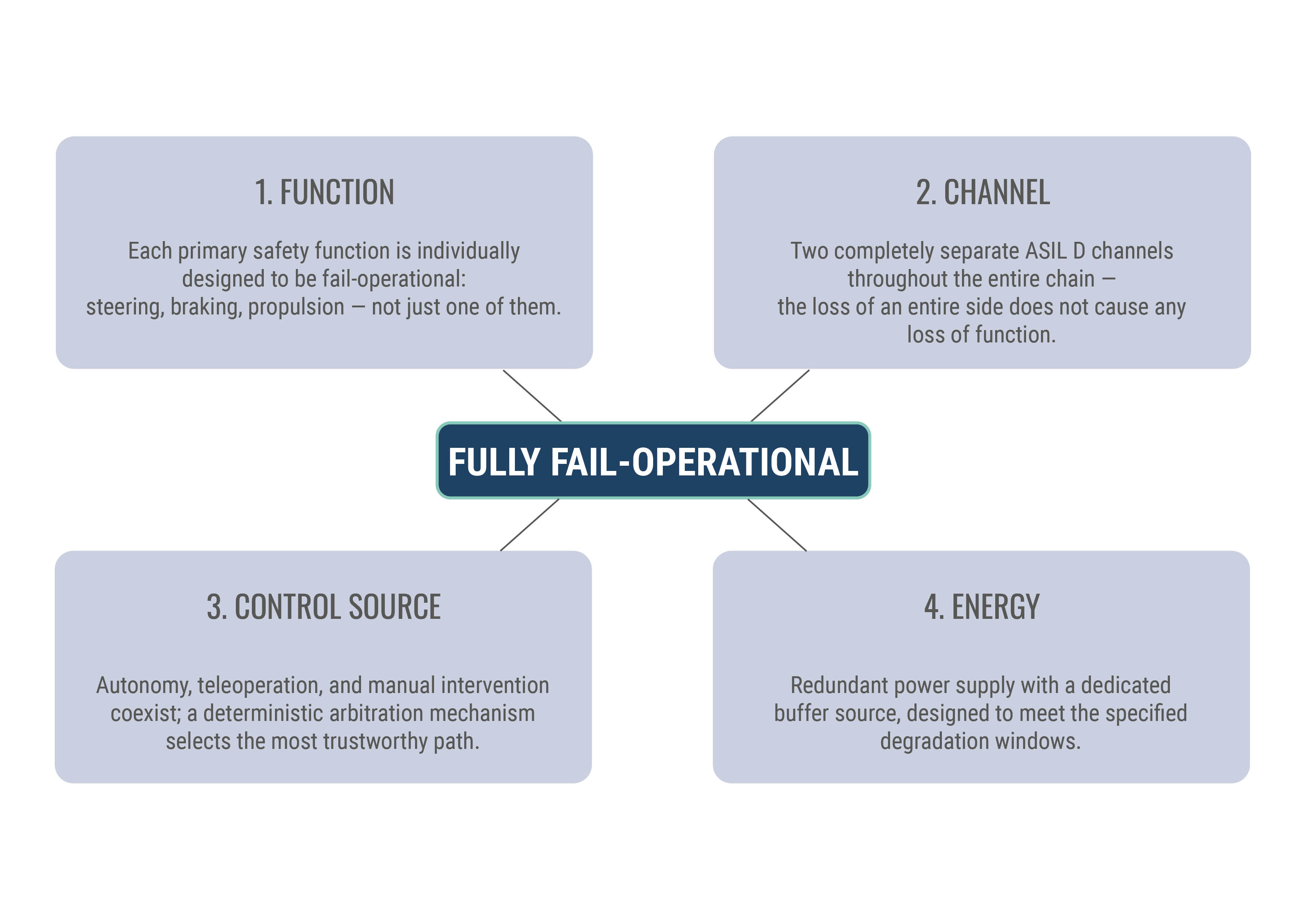
“Fail-operational” is a convenient term for data sheets—and a challenging one for architects. It only becomes robust once the question “operational relative to what?” is fully answered. That is why, at Safety-by-Wire®, we speak of Fully Fail-Operational. The following comparison shows what makes the difference on each of the four axes—on the left, what is often already considered “fail-operational” in practice; on the right, the standard we set for the platform:
Axis | Common oversimplification in practice | Fully Fail-Operational |
|---|---|---|
| Function | One function—usually steering—is designed with redundancy; for the rest, the shutdown logic still applies. | Each primary safety function is designed to be fail-operational individually: steering, braking, propulsion. |
| Channel | Two channels, but with a tiered design or shared components. | Two completely separate ASIL-D channels throughout the entire chain—from sensors to actuators, with less than 10 FIT per channel. The loss of an entire side does not result in a loss of function. |
| Control source | One control source; the human operator remains the silent fallback. | Autonomy, teleoperation, and manual intervention coexist; a deterministic arbitration mechanism selects the most trustworthy path at all times. |
| Power | Two power supply paths—without a dedicated buffer source. | Redundant power supply with a dedicated buffer source, designed for the specified degradation windows. |
Only when all four axes are covered does a platform deserve the attribute “Fully Fail-Operational.” And only then does the architecture fulfill the target catalog from Part 2—in every domain for which it was formulated. A note on terminology is in order: “Fully Fail-Operational” is not a category defined in the standards, but a deliberately narrower definition that we propose as a verifiable property—measurable along precisely these four axes.
What OEMs, integrators, and operators should clarify now
- What is the defined safe state for their own application—immediate shutdown on-site or controlled continued operation until a safe stop? And who determined this?
- Is redundancy maintained throughout the system—or do two channels terminate at a shared connector, power supply, or bus system?
- How does the system determine which path is correct—is there voting and diagnostics at all levels, including for latent faults?
- What degradation levels are defined—and have the transitions been tested under real-world conditions, not just specified?
- Do the power and communication supplies follow the same safety logic as the function itself?
These questions determine the architecture—and architecture cannot be patched. If you don’t ask them until the integration project, all you can do is document what’s already there. That’s why Arnold NextG answered them before the first circuit board was designed: The fully fail-operational structure is the core of the platform’s preliminary development, not just an add-on.
Conclusion
The elimination of the driver as a fallback is not a minor detail of automation—it is its architectural core. Anyone who takes this seriously will inevitably arrive at end-to-end redundancy, controlled degradation, and a level of completeness that encompasses all four axes. “Fully Fail-Operational” is then no longer a promise, but a structural property.
In the fourth and final part of this series, we’ll show how this architecture is verified: from FMEDA and fault tree analysis through independent assessment to validation in real-world operation—and why verification doesn’t end with the start of production.